Customer Satisfaction Starts with the Right Antenna
By Mike Branch, Decibel Products
Antenna Selection
Rural Requirements
Urban Requirements
New Technology
Continued Evolution
Whether it's with associates out in the field or coworkers around the water cooler, you are probably all discussing the same issues that face today's wireless networks—co-channel interference, signal drop-off, and capacity. With the explosive growth of cellular phones and the Internet, these are key issues you must address to facilitate growth and maintain customer satisfaction. If these issues are not addressed, overloaded network systems promise to become increasingly crowded, leading to signal degradation, frustrated customers, and eventual loss of business.
Antenna Selection (Back to top)
With this in mind, today's wireless network engineers must continually work to find reliable, expedient solutions that are specifically designed to increase capacity, reduce signal drop-off, and eliminate co-channel interference. One way of doing this is by remaining cognizant of the importance of antenna selection. By fully understanding your site and wireless network needs, it is easy to select an antenna that eliminates these problems and provides a stable base for reliable performance.
Antenna selection is possibly the most critical decision an engineer can make when designing a solution that meets today's wireless challenges. The first issue you should address is determining what horizontal beamwidth is best for your site requirement. Networks are designed for two basic areas — rural and urban. Both are vastly different and feature separate coverage requirements.
Rural Requirements (Back to top)
Wide open spaces, limited city access, and roads stretching for miles are all characteristics of rural wireless networks. Because there are fewer obstructions, primary emphasis is placed on maximizing the distance covered by the RF signal, although this can vary depending on customer needs and individual site requirements.
For this reason, beamwidths of 30° - 45° are typically used to maximize distance with fewer towers. To further increase distance, companies have developed innovative technologies to boost power and extend signal range (see Figure 1). These new antennas deliver proven electrical performance with little loss of gain at the frequency band edges and an excellent voltage standing wave ratio (VSWR). At the same time, they provide exceptional front-to-back ratios for optimal coverage in rural networks.
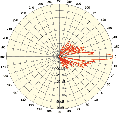
Figure 1. Innovative high-gain technologies have been developed over the past several years to maximize rural coverage.
Urban Requirements (Back to top)
The requirements for urban wireless networks are a direct contrast to those found in rural regions. Open spaces are limited, population bases are larger, and wireless usage is at a maximum. As a result, emphasis is now placed on signal transmission control and where it is directed. In addition, signals must also be strong enough to penetrate buildings, parking garages, and other large obstacles effectively while still providing clear, reliable communications for wireless users.
Urban environments pose three primary problems, including interference from adjacent cell sites, sector-to-sector interference, and the "ping pong" effect. In the latter, a cellular signal is unable to determine what sector to stay on, causing it to bounce between multiple sectors constantly. In addition to degraded signals and dropped calls, it clogs sector space and overloads relays, resulting in busy signals and long connection periods for cellular users attempting to make calls. As a result, precise, targeted beamwidths are better within these environments.
New Technology (Back to top)
Base station antennas suitable for this type of urban application include those models designed with array tapering, which optimizes upper side lobe suppression and null-fill (see Figure 2). At the same time, the industry is moving rapidly toward printed circuit board technology, which provides superior intermodulation, reliability, and maximum control with minimal signal loss. Although relatively new, printed circuit board technology is ideal for use in highly congested urban environments where competing wireless signals frequently overlap and compete for the same airspace with narrow frequency separation.
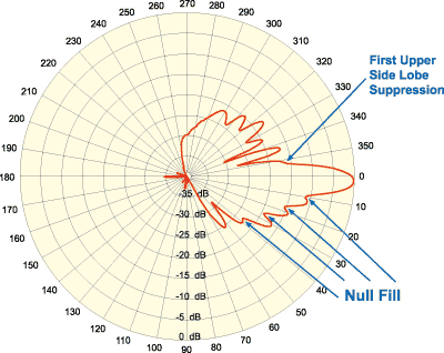
Figure 2. A maximum null fill pattern with 2º electrical downtilt is ideal for urban coverage.
Although typical highway coverage is 30° to 45°, short distance urban needs are currently met with 65° to 90° beamwidths (see Figures 3 and 4). As with rural settings, new technology has also been recently developed to improve urban signal quality as well. Those antennas using Decibel Products' MaxFill technology provide upper side lobe suppression greater than 18 dB down from the main beam and null-fill of less than 15 dB down from the main beam. This allows consistent null fill across the entire bandwidth, making the signal more precise.
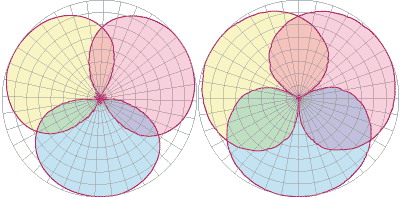
Figures 3 & 4. Maximum null fill achieved by using a 65º, three-sector pattern (left) Maximum null fill achieved by using an 85º, three-sector pattern (right)
By operating on a unique feedline system that creates an exceptionally well-defined pattern, this enhancement slashes co-channel interference and bolsters weak signals while eliminating gaps in coverage and focusing more valuable energy below the main beam toward wireless users.
Continued Evolution (Back to top)
Although co-channel interference, signal drop-off, and capacity issues all remain concerns for the wireless industry, the evolution of antenna technology has created a number of viable solutions to effectively deal with them. The continued study of antenna patterns—driven by the explosion of wireless use over the past decade—has played a key role in spawning technology that minimizes, if not eliminates, these problems.
Indeed, antenna technology has seen dramatic advances since the cellular 360° omnidirectional antenna was introduced in the early 1980s. Since then, surging cellular use and problems associated with signal overlap quickly led to the development of sectorized 120° and 105° antennas in rapid succession. Finally, in just the last year, the industry has begun a noticeable shift to 65° to 90° beamwidth antennas specifically designed for sites located in the core of wireless network systems (see Figures 5 and 6).
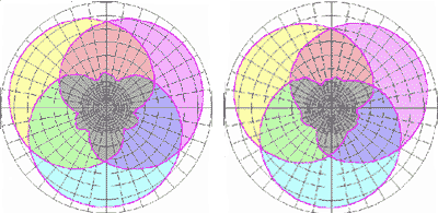
Figures 5 & 6. Wireless signal coverage and overlap of a 90º, three-sector pattern using standard technology (left) Wireless signal coverage and overlap of a 70º, three-sector pattern using standard technology (right)
Despite this rapid advancement in technology, there still remains no single answer when dealing with co-channel interference, signal drop-off, and capacity issues. However, it is important to know that costly solutions are not necessary if you can eliminate potential problems at the beginning. By identifying the core requirements of your site and by understanding the importance of antenna selection, you can improve network performance. In the process, you will ensure increased reliability, added productivity, and enhanced customer satisfaction.
About the Author (Back to top)
Mike Branch is vice president of sales & marketing for Decibel Products. He can be reached at Decibel Products, 8635 Stemmons Freeway, Dallas, TX; 214-819-4383; mbranch@decibelproducts.com.
